Physical Computing Class at City of Bridges High School, Pittsburgh

About this class
City of Bridges High School is a “progressive, holistic, 9th–12th grade high school which believes that school should be transformational for the students, the community, and the world.” (I couldn’t put it better than them!) They’re located on the South Side of Pittsburgh, PA.
Robert Zacharias (that’s me) is teaching a five-week class there on Physical Computing in the spring of 2020. The class runs on Tuesday and Thursday afternoons, 1–3 p.m. We’re learning how to build interactive electronic devices using the Arduino electronics platform.
Our goals for the block
- Learn some electronics theory and practice.
- Learn some programming in the
Clanguage. - Learn to use the Arduino electronics platform to build simple interactive devices (which combine electronics and computer programming).
- Use our newly acquired skills to create some data-gathering devices—i.e. experimental apparatus—to be used in scientific inquiry by City of Bridges students.
Assignments
| assignment | due |
|---|---|
| Homework 1 | Tuesday 2/11 (extended from 2/6) |
| Homework 2 | Tuesday 2/18 |
| Homework 3 | Thursday 2/20 |
| Homework 4 | Tuesday 2/25 |
| Homework 5 | Thursday 2/27 |
| Homework 6 | Tuesday 3/3 |
Progress log
As of this writing (Thursday, March 5th, 2020), this class has concluded. Thanks to the students and staff of City of Bridges High School for sharing in the learning. I’m hoping that this experience will serve as a useful kernel for further explorations in electronics, software, and building interactive devices.
Here’s a log of the learning and activities we did every day in our time together:
Class 1: Tuesday, February 4th
- Getting to know each other: what is everyone’s name, and what’s an example of something you recently built or like to build?
- Introduction to the teacher and some sample projects his CMU students have made in the past
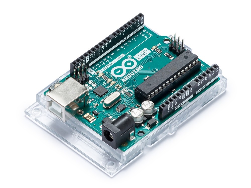
- Going on a slow and patient tour of the Arduino Uno board and its many different components, including:
- capacitors which are mounted on the board
- direct current (DC) input power barrel jack
5V(5 volt) andGND(ground) pins- the Analog Input section, which are pins
A0throughA5 - the 16 MHz (megahertz) crystal oscillator which helps keep the Arduino’s chip coordinated
- the ATMega 328 chip which is the heart and brains of the Arduino
- the Digital Input/Output (I/O) section, which are pins
0through13- note: pins
0and1are reserved for communication, and you shouldn’t plug into them unless you’ve got a pretty good reason
- note: pins
- various indicator lights on the board, including the power light, the TX and RX lights, and the light connected to pin
13 - the reset button
- the USB port
- Introduction to algorithms activity
- Cut/tear a piece of paper into different-length rectangles
- Lay these in a random order on the table in front of you
- Put them in height order.
- How did you do that? What were the “rules” you followed?
- Sharing out some student-generated suggestions for other rules (i.e. sorting algorithms) to put things into an order
Class 2: Thursday, February 6th
- Briefly go over Homework 1 responses (only two students completed it! Hence the extension to Tuesday 2/11)
- One student selects this beautiful image of magnetic force lines “because it looks like a pair of eyes in the darkness.” We use this as a jumping-off point to talk about magnetic fields broadly; how the Earth itself is a magnet which has changed over time; and how likes repel while opposites attract (one of the many parallel phenomena to those we see in electronics).
- Another student points to a site covering a brief history of automated electrical defibrillators (AEDs), and we briefly discuss the historical development of these devices from odd experiment to commonplace lifesaver.
- The “hydraulic analogy” for electrical flow.
- Pressure creates flow. More pressure creates more flow, and vice versa. These two have a “direct relationship.”
- Resistance fights against flow. At a fixed pressure, more resistance creates less flow, and vice versa. These two have an “inverse relationship.”
- An experiment: we hand out a long and short piece of straw to some students. The students are asked to blow through each straw separately and describe the difference in sensation.
- Students uniformly report that blowing through the longer straw is more difficult, and that less air flows when they blow with a certain force. (This straw is more resistive.)
- Conversely, blowing through the shorter straw is easier, and that more air flows when blowing with a certain force. (This straw is less resistive.)
- These findings reinforce experimentally what we’d already decided in theory about the relationship between pressure, resistance, and flow.
- Drawing electrical schematics
- Use of a common set of shared symbols and drawing conventions leads to clear communication of circuits between engineers.
- Elements we draw and name:
- wire/trace
- ⏧ node (two or more wires joining)
- crossing without contact
- diode
- light-emitting diode (LED)
5Vpower supply- ⏚ ground
- simple switch
- resistor
- Exercise: given a
5Vsupply, a ground, and an LED, draw the proper connecting wires to make it so the switch turns the LED on and off.- Two solutions:
5V—switch—LED—ground, or5V—LED—switch—ground. - In both cases, as we discuss, operating the switch will complete or interrupt the circuit (and therefore can be used to switch the LED)
- Two solutions:
- Practical application: wiring up an LED using the Arduino as a power supply
- Learning how a solderless breadboard’s internal wiring is structured
- No switch this time, but we do use a resistor to prevent too much current from flowing through the LED
- The circuit is
5V—resistor—LED—ground
Class 3: Tuesday, Febuary 11th
- Cell phone policy: please don’t use cell phones in class!
- Timing: if we start class on time, we can take a 5 minute break in the middle.
- Go over further homework responses
- Reviewing schematics from last class
- Circuit activity: using the continuity meter
- Break
- Arduino programming (see below for the code we wrote today in class)
// make the light attached to pin 13 blink

/*
 * the steps to make a light blink:
 *
 * 1. turn the light on
 * 2. turn the light off
 * 3. repeat 1 and 2
 *
 */

// stuff you want to do once and only once
void setup(){
  // set up the correct pin modes
  pinMode(13, OUTPUT); // OUTPUT is like a power supply
}

// stuff you want to do over and over
void loop(){
  // turn on the LED
  digitalWrite(13, HIGH); // "send electricity out of pin 13"

  // wait for half a second
  // delay(XXX) milliseconds (there are 1000 milliseconds per second)
  delay(500);

  // turn off the LED
  digitalWrite(13, LOW); // "don't send electrity out of pin 13"
  delay(200);
}
Class 4: Thursday, February 13th
- Flow and resistance
- Pressure (or voltage) falls along a resistive path
- This is true in the case of a pipe carrying a fluid, or a wire carrying electricity
- Materials have different electricity-carrying capacity
- Insulators conduct electricity poorly (air, stone, wood, brick, glass, etc.)
- Conductors conduct electricity well (metals)
- Semiconductors are somewhere in the middle (graphite, silicon, and others)
- A potentiometer is a three-legged component
- One outside leg connects to a voltage source
- The other outside leg connects to a different voltage (typicall ground)
- The middle leg, called the “wiper,” can be connected electrically at any point along that resistive path, so its voltage can be varied by the user from the input voltage on the left, to the input voltage on the right, or anywhere in between
- Designing and implementing a circuit to use a potentiometer to dim the brightness of an LED
- A multimeter is an electrical tool that can measure:
- Voltage, and when it’s doing this it’s called a “voltmeter” (we use it in class to measure the voltages present at different points in our circuit)
- Resistance, and when it’s doing that it’s called an “ohmmeter” (we use it in class to measure the resistance of a wire, our own bodies, and a potentiometer)
- The Arduino is a voltmeter; here’s some code to read the voltages it reads on an analog input pin:
// read a potentiometer value and send it back to the computer

/*
 *  potentiometer wiper is connected to pin A1
 *  potentiometer outside legs are connected to 5V and ground
 */

void setup(){
  pinMode(A1, INPUT);
  // turn on the Serial communication system
  Serial.begin(9600);
}

void loop(){
  // Serial.println(thingInHere) will "print" thingInHere to the computer
  Serial.println( analogRead(A1) ); // measure the voltage at pin A1
}
Class 5: Tuesday, February 18th
- Briefly go over Homework 2
Partial example solution:
void setup() {
  pinMode(2, OUTPUT);
  pinMode(3, OUTPUT);
  pinMode(4, OUTPUT);

  digitalWrite(2, HIGH);
  digitalWrite(3, HIGH);
  digitalWrite(4, HIGH);
  delay(400);

}

void loop() {
  digitalWrite(2, LOW);
  digitalWrite(3, LOW);
  digitalWrite(4, LOW);

  delay(400);
  digitalWrite(2, HIGH);
  delay(400);
  digitalWrite(2, LOW);
  digitalWrite(3, HIGH);
}
- Review schematics from homework
I = V ÷ Rand its implications (using the math to find unknown current, resistance, or voltage)- The Arduino is a voltmeter activity
- Use the potentiometer to change blinking rate of two LEDs
- Add on a photoresistor to measure the amount of ambient light, and use that to also vary the blinking rate
- Brief introduction to block diagrams, for use in Homework 3
// read a potentiometer's value and send it back to the computer
// use the potentiometer's position to change blink rate

// pot is plugged in to pin A3
// LED1 is plugged into pin 3
// LED2 is plugged into pin 5
// photoresistor is plugged in to pin A1

void setup() {
  pinMode(A3, INPUT);
  pinMode(A1, INPUT);
  pinMode(3, OUTPUT);
  pinMode(5, OUTPUT);
  Serial.begin(9600); // turn on serial communication between Arduino and computer
}

void loop() {
  Serial.println( analogRead(A3) ); // send analogRead(A3) back to the computer
  // turn on one LED and turn off the other
  digitalWrite(3, HIGH);
  digitalWrite(5, LOW);
  delay(analogRead(A3));

  // switch which LED is on and off
  digitalWrite(3, LOW);
  digitalWrite(5, HIGH);
  delay(analogRead(A1));

}
Class 6: Thursday, February 20th
- Going over answers to Homework 3
I = V/Rmath/circuit problems- Block diagram schematics of various machines or processes
- Resistors in series add up their equivalent resistances, while resistors in parallel reduce their equivalent resistances
- Wiring up a button using a pull-down resistor so that the input is not left floating
- Using variables in our code (see sample code below)
- The all-important
if…elsestructure in programming to test for conditions - Homework assigned: Homework 4
Code we wrote: turning on an LED when an attached button is pressed (Note: I added the lines which make the POTPIN variable)
// button plugged into pin 2
// and LED plugged into pin 6

// make a new variable to store the pin number
int BUTTONPIN; // BUTTONPIN is the name of the variable.
BUTTONPIN = 2; // now BUTTONPIN stores the number 2.
int LEDPIN;
LEDPIN = 6;
int POTPIN = A0; // you can also do these both in one line

void setup(){
  pinMode(BUTTONPIN, INPUT);
  pinMode(LEDPIN, OUTPUT);
  pinMode(POTPIN, INPUT);
}

void loop(){
  // when the button is pressed, light the LED

  int buttonState; // variable to store the button's state
  buttonState = digitalRead(BUTTONPIN);

  int potVal; // variable to store the potentiometer's value
  potVal = analogRead(POTPIN);

  // test: are there 5 volts at pin 2?
  if ( buttonState == HIGH ) {
    // if so, then light pin 6
    digitalWrite(LEDPIN, LOW);
  } else {
    // if not, turn off the light
    digitalWrite(LEDPIN, HIGH);
  }
}
Class 7: Tuesday, February 25th
- Reviewing Homework 4
- One student did the ideation assignment
- Students had a hard time with the technical assignment
- We do the “technical warmup” assigned
- Driving a small speaker with the
tone()library - Reading an HC-SR04 ultrasonic ranger using the
NewPinglibrary (downloaded via Library Manager) - Driving a hobby servomotor
- Homework 5 assigned
Code to do the technical warmup homework assignment:
// alternating blinking LEDs, rate based on a pot. position

const int LED1PIN = 4;
const int LED2PIN = 3;
const int POTPIN = A0;

void setup() {
  pinMode(LED1PIN, OUTPUT);
  pinMode(LED2PIN, OUTPUT);
  pinMode(POTPIN, INPUT);
}

void loop() {
  int potVal = analogRead(POTPIN);

  digitalWrite(LED1PIN, HIGH);
  digitalWrite(LED2PIN, LOW);
  delay(potVal);

  digitalWrite(LED1PIN, LOW);
  digitalWrite(LED2PIN, HIGH);
  delay(potVal);
}
Code to drive a hobby servomotor:
// tell a servo motor where to go

#include <Servo.h>
const int SERVOPIN = 3;
Servo turnMotor; // create a servo motor "object"

void setup() {
  turnMotor.attach(SERVOPIN);
}

void loop() {
  turnMotor.write(5); // go to 5 degrees of rotation
  delay(500);
  turnMotor.write(100); // go to 100 degrees of rotation
  delay(500);
}
Class 8: Thursday, Feb. 27th
- Review Homework 5
- Everyone shares out their proposals for scientific apparatus to build out for the final project (part 1 of the homework). Note that many of the ideas weren’t “apparatus” per se, but rather useful daily-life implements. Ideas students presented:
- An intercom system to operate between rooms at City of Bridges
- A system that would acknowledge when people make donations to the community fridge (a fund for purchasing communal food)
- A speaker that would play a predetermined song (such as the birthday song, etc.)
- A water temperature sensor
- A weather station
- An air quality monitor
- An alarm clock device, preprogrammed to alarm at particular times of day relevant to the City of Bridges school day (such as between classes)
- A distance-sensing aid for a blind or visually impaired person (using an ultrasonic ranger to provide tactile distance feedback)
- A sound machine to play different soothing (i.e. white noise) sounds at different times
- A rain gauge
- A multi-input weather station
- Student shows off their input–output machine (part 2 of the homework)
- A device that illuminates an LED when an ultrasonic ranger detects an object inside of a particular range
- Everyone shares out their proposals for scientific apparatus to build out for the final project (part 1 of the homework). Note that many of the ideas weren’t “apparatus” per se, but rather useful daily-life implements. Ideas students presented:
- Quick demo of a 16-column, 2-row alphanumeric LCD display (like this one)
- We learn how to use the ADXL335 triple-axis analog accelerometer (tutorial page for reference)
- Some wrestling with our computers and their Bluetooth keyboards which are annoying to pair with them (this unfortunately consumed ~20 minutes of class)
- Discussion of our final project plan
- Sole apparatus proposal: weather station
- Daily-life helpful proposals: community fridge donation reward machine; song-playing speaker system; pre-programmed alarm clock
- After some discussion, it emerged that dividing our energies into multiple projects would probably stretch our efforts too thin
- In conclusion: We’re building a weather machine!
- Homework 6 spells out exactly who is working on what to bring to class on Tuesday, with the intention of integrating the different parts into a working whole
Code we wrote to read the ADXL335 accelerometer values is below. This code will print values on the computer in the format 356,389,274 per a single-line record, where the comma-separated values are the X, Y, and Z accelerometer values respectively.
// read a three-axis accelerometer

const int XPIN = A0;
const int YPIN = A1;
const int ZPIN = A2;

void setup() {
  pinMode(XPIN, INPUT);
  pinMode(YPIN, INPUT);
  pinMode(ZPIN, INPUT);
  Serial.begin(9600);
}

void loop() {
  Serial.print( analogRead(XPIN) );
  Serial.print(",");
  Serial.print( analogRead(YPIN) );
  Serial.print(",");
  Serial.println( analogRead(ZPIN) );
}
Class 9: Tuesday, March 3rd
- Reviewing Homework 6 progress…unfortunately, this was harder than anticipated and nobody came in with a working model.
- Putting the pieces together to drive different outputs (one output per team) with the photoresistor input.
- Learned the
map()function (discussed in Homework 5 but not yet elaborated on in class) very useful in facilitating a single input value driving different output devices with different ranges. - Teams assigned for final project development:
- Akhil + Cain: LCD screen output
- Austin + Fé: RGB LED output
- Husayn + Stevin: servo motor gauge output
- Kai + Phoenix: speaker output
- Each team had by the end of class gotten at least one input to drive their own output.
- Decisions reached about the weather machine’s signal–output mapping:
- PM2.5, thermometer, and photoresistor → LCD screen output
- PM2.5 → servo gauge output
- thermometer → RGB LED output
- photoresistor → speaker output
We wrote some code to read a photocell as an input and use its value to write to various different outputs.
// read the value of a photoresistor
// and send its value to the computer
// and also drive a ________________

const int PHOTOPIN = A0;
const int SERVOPIN = 4;

void setup() {
  pinMode(PHOTOPIN, INPUT);
  pinMode(OUTPUTPIN, OUTPUT);
  Serial.begin(9600);
}

void loop() {
  int potVal;
  potVal = analogRead(PHOTOPIN);
  Serial.println(potVal);

  int outputVal; // create an output value
  // use map() to change the range of the output value
  outputVal = map(potVal, 21, 900, 0, 180);


  delay(100);
}
Class 10: Thursday, March 5th
- Our final build day!
- Status check-in to start: things were about where we last left them on Tuesday
- Then, establish quick work plans for each student and team:
- Austin + Fé: finish thermometer input and LED output. Problem: apparently both TMP36 sensors we had on hand were malfunctioning (perhaps they were wired with reverse polarity at some point—unclear). Solution: change to accelerometer as input rather than thermometer.
- Akhil + Cain: finish LCD display code. Problem: displaying
ºdegree symbol inºFdata label; solved withlcd.write(223)command. Hand-drew a map of all the character positions in a 16×2 matrix to clarify how to formlcd.setCursor(x,y)commands. - Stevin + Husayn: build out physical servo gauge. (Their code was already complete and functioning at the start of class.)
- Phoenix: plan out and build the physical layout for the combined electronics.
- Kai: complete the photocell-to-speaker subsystem and prepare it for integration into the main system.
- After our 5-minute break, students wrote out a shared main schematic for the complete system:

(Stevin drew the blue, Austin drew the orange, and Kai drew the purple. I drew the black.)
- Combining all hardware together onto the same breadboard and Arduino (each team contributed their piece)
- Combining all software together into one sketch (Akhil and Stevin worked together on this)
- Final show-off at about 3:00 p.m.…worked only very intermittently, unfortunately. But that’s pretty par for the course in assembling everything and then immediately testing. I suspect an electrical problem based on the intermittency we observed. This could be debugged by unplugging individual components and doing unit tests, which is what we would’ve done systematically if we had more time.
- Having gotten as far as we could in the time given, we called it a day, did our group appreciations, and sic transit gloria mundi.