Physical Computing Class at City of Bridges High School, Pittsburgh
Homework 3
both parts due at the start of class on Thursday 2/20
Part 1: Diagramming
Block diagrams
A block diagram (Wikipedia page) can mean different things in different engineering specialties. For us, though, it’s going to be a simply-executed drawing which illustrates the flow of information, or data, through a system.
Here is an information flow block diagram that shows a representation of the system that controls access to the front door of the CoB building:
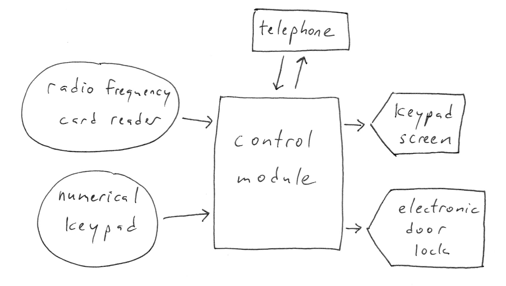
In general, sensors will output data (we’ll draw them as circles), and actuators will accept input data (we’ll draw them as pointed pentagons). In this case, both the keypad and RFID reader are sensors, and the electronic lock mechanism is an actuator.
There are two elements which we’ll draw as rectangles: the control module and the telephone. Both of these are devices which have some complex internal controls or programmability, and which can serve as both inputs and outputs.
Assignment
Draw three block diagrams, each describing a system you’re familiar with. Use the drawing above as an example for style and format. Some starter ideas of the sorts of systems you might choose to diagram:
- a traffic light with a walk signal
- a vehicle
- a computer
- a cell phone
- the economy
- a microwave
- a gasoline pump
- a light switch
Additionally, draw one block diagram for a machine you’d like to make. At the heart of your machine will be an Arduino. The sensors and actuators are your choice.
Part 2: Ohm’s Law
A few Ohm’s Law math problems for homework. These are just meant to get you practicing the math a little bit, but if you’re feeling like you can’t finish them, just get as far as you’re able.
There are some conventional symbols that are used in physics when stating Ohm’s Law, and they have equivalent units that are used in electrical engineering:
| measurement | physics symbol | electrical engineering symbol and unit |
|---|---|---|
| current | I |
A for amp |
| voltage | V |
V for volt |
| resistance | R |
Ω (Greek letter omega) for ohm |
First, a refresher: Ohm’s Law can be stated in a few ways. The way we’ve learned it in class is:
I = V ÷ R
or
A = V ÷ Ω
which could be thought of as “the amount of current flowing is equal to the amount of voltage pushing, divided by the amount of resistance fighting against it.” This form of the equation is great if you’re trying to solve for I (current).
However, if we are interested in solving for an unknown voltage, the same equation can be rearranged instead to read:
V = I × R
or
V = A × Ω
And likewise, the equation can also be rearranged to solve for an unknown resistance:
R = V ÷ I
or
Ω = V ÷ A
By rearranging the equation these three ways, we can mathematically isolate an unknown value and calculate it as a function of the other two known values.
Problems
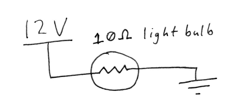
1) How much current will flow through the circuit as shown? State the answer in amps as well as milliamps. (One amp contains 1,000 milliamps.)
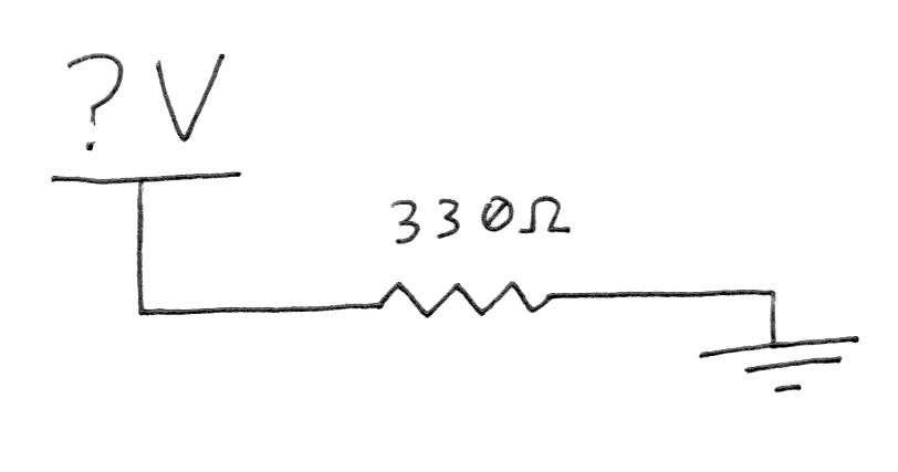
2) How much voltage will be needed to push 12mA through the resistor in this circuit?
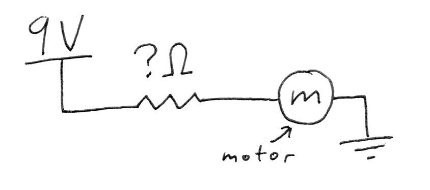
3) What resistor value should you select to limit the current flow through this motor to only 2A?
4) Draw your own circuit below, with a single unknown, and then do the math to find its value.